Background
Engine air intake must supply the required mass flow rate to the engine with the minimum total pressure losses and flow distortions. This is vital to the performance and stability of engine operation. For turboshaft engines, the airflow at the engine face, often referred to as Aerodynamic Interface Plane (AIP), must have a relatively low Mach number: therefore, the engine inlet must be designed to act as a diffuser with reasonably gentle diffusion from flight Mach number to a lower Mach number. Moreover, inlet flow distortions at AIP must be compliant with the limits defined by the engine manufacturer. In addition, the external flow is none-the-less important to the aircraft aerodynamics, primarily to aircraft drag. As such, the inlet must be designed to prevent boundary layer separation, even when the axis of the intake is not aligned with the streamline direction far upstream, as is often the case when helicopter air intakes are considered.
Regarding the exhausts, unlike a basic turbojet, the exhaust velocity of the core in a turboshaft engine is low and contributes little to thrust since most of the energy goes into turning the drive shaft. In addition, the exhaust nozzle is a relatively easy component to be designed from a fluid-dynamic standpoint, since the pressure gradient is usually favourable all along the walls. However, the layout of the exhaust system, whose typical configuration is an S-shaped duct, is responsible for difficultly predictable flow fields. Hence, proper design criteria are needed to correctly size the exhaust system.
Strategy
In HEAVYcOPTer, a robust procedure was implemented including geometry parameterization, meshing, geometrical/grid manipulation, as well as CFD analyses into an automatic design optimization loop for both intakes and exhausts of AW101 helicopter. In particular, the proprietary optimization tool GeDEA, which is capable of efficiently handling complex multi-objective problems, was applied to review the basic intake and exhaust design, with the aim of minimizing any detrimental effects on both drag and engine installation, through both a reliable intake and exhaust shaping and an analysis and control of flow distortion, total pressure losses and flow separation. Finally, the optimized engine installation geometry was checked for compliance with feasibility constraints in order to accomplish industrial needs for prototyping and testing.
Outcomes
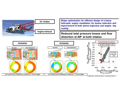
The performance of both AW101 lateral and central intakes was enhanced by reducing the total pressure losses and the inlet flow distortion at the engine interface at two relevant flight conditions, i.e. hover and forward flight. The optimization made it possible to achieve remarkable improvements on the main performance parameters and to obtain an enhanced aerodynamic behaviour. In fact, the optimised lateral intake configuration featured a 25% drop in total pressure loss in hover and a -33% reduction in cruise, respectively. For central intake, the optimized geometry was characterised by a 25% reduction of total pressure loss in forward flight, accompanied with an increment of 11% at hovering. In addition, both the intakes were compliant with the flow distortion functional constraint at forward flight conditions.
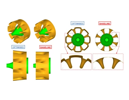
Regarding the exhaust optimization, the main objective was the minimization of engine back pressure, while the second objective was used to constraint the entrainment ratio to values close to the baseline, in order to meet the fire extinguishing system requirements. The finally selected optimal design was characterized by a 22% total pressure loss reduction in cruise with respect to the baseline, with a difference between entrainment ratio of optimized solution and the baseline less than 4%. In addition, some further aerodynamic characteristics of the engine installation, like for instance potential tailboom heating, potential re-ingestion of hot gases in ground idle conditions, and effect of rotor inflow in some representative flight conditions were taken into account and assessed.
Duration: April 2011-March 2013
This project has received funding from the Clean Sky Joint Undertaking (JU) under grant agreement No. 278416


